Liberty II Product Orientation
Time Required for Assembly |
1 hour |
Overview
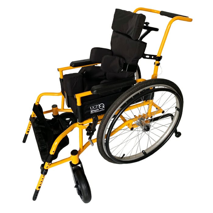
• The Liberty II is a pediatric wheelchair with postural support.
• Intended for children with mobility limitations who also need postural support to sit upright, balanced, and comfortable.

Important! Please read before assembly:
- Before starting to assemble the wheelchair, please make sure to identify all the contents of each carton.
- Pay special attention to the different screws, bolts, nuts, and washer sizes. Click here for a complete list of parts included in each package.
- Each screw and bolt size has a specific place in the assembly. Please read the instructions carefully for where to install each screw and bolt.
- Arrange items by type and size. Having the same items together makes it easier to count for stock control and reordering.
- Small items, such as screws, nuts, and washers may be kept in small boxes, one for each type and size. Mark the name of the item on the front of the box.
Packaging and parts
The Liberty II is packed in two cartons, one for the frame and one for the seat unit.
Tools needed
- 10mm open-end wrench (included)
- 10mm socket wrench (included)
- Phillips screwdriver (included)
- Foam knife (available with the Modification Kit)
Parts included for the frame assembly
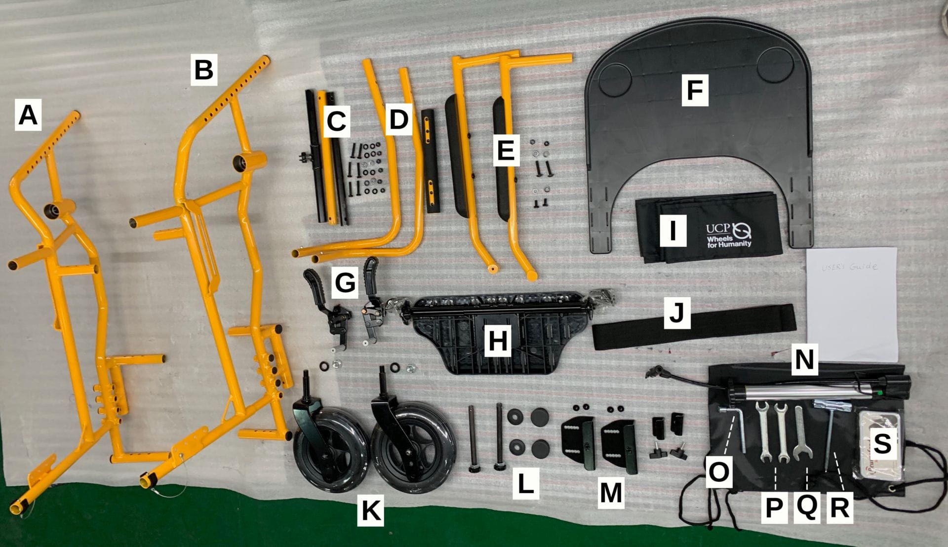
A. Left frame
B. Right frame
C. Central frame tubes and hardware (to attach right and left sides)
D. Push handles
E. Armrests and hardware
F. Tray
G. Wheel locks
H. Footrest
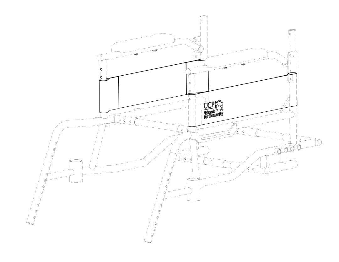
I. Side guards
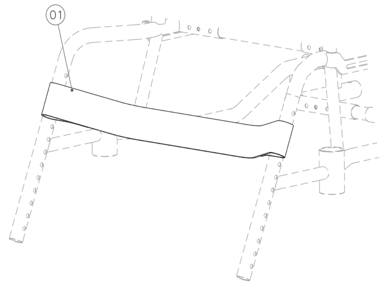
J. Calf strap
K. Front casters
L. Rear wheel axles and covers
M. Tray lock mechanism and hardware
N. Air pump
O. 10mm socket
P. 2 13mm and 10mm open-end wrenches
Q. 19mm open-end wrench
R. Phillips screwdriver with 17mm and 19mm socket
S. Flat tire repair kit
Parts included for the seat unit assembly
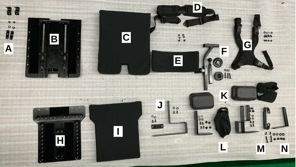
A. Seat clamps
B. Seat pan
C. Seat cushion
D. Pelvic strap
E. Headrest
F. Headrest mount attachment
G. Chest harness
H. Backrest pan
I. Backrest cushion
J. Seat-to-backrest attachment and hardware
K. Lateral support pads and covers
L. Lateral support attachments and hardware: “L” brackets and “U” brackets with hardware
M. “U” back-to-frame post brackets
N. “L” backrest pan brackets
Section 1: Frame Assembly
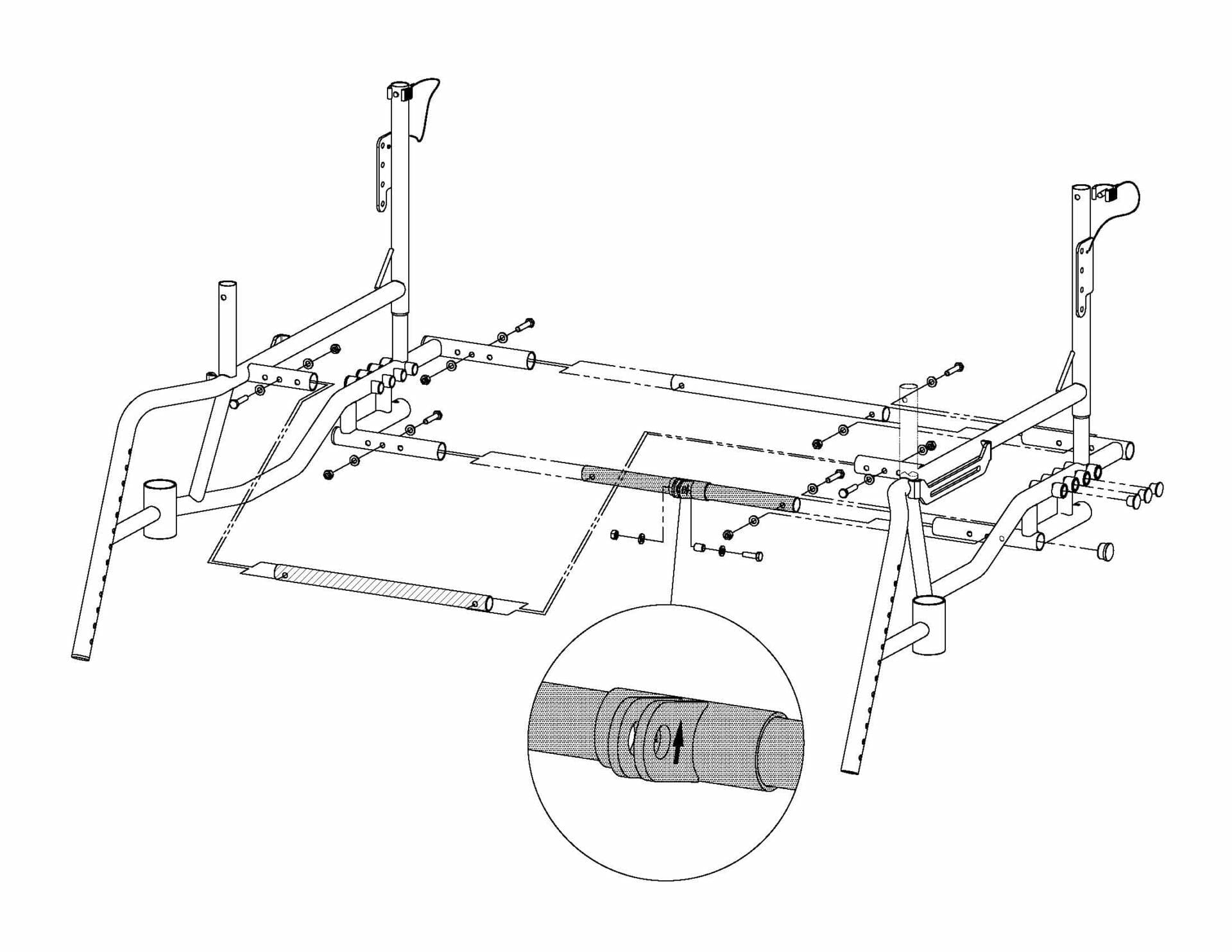
Step 1: Frame tubes
Tools required
• 10mm open-end wrench
• 10mm socket wrench
Parts required
• 6 M6 hex head cap screws 30mm long
• 12 M6 washers
• 6 M6 nylon lock nuts
Instructions
• Connect the right and left frame tubes with the 3 center tubes and 6 screws, washers and nuts. Screw head should be pointing outward. Tighten snugly.
• Make sure to select right frame size by using the corresponding frame holes (small, medium or large).
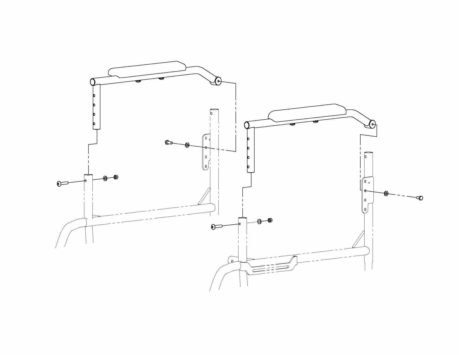
Step 2: Armrests
Tools required
• 10mm open-end wrench
• 10mm socket wrench
• Phillips screwdriver
Parts required
• 2 M6 hex head cap screws 10mm long
• 4 M6 washers
• 2 M6 nylon lock nuts
• 2 M6 Philips pan head screws 30mm long
Instructions
• Attach the armrest tubes to the frame using the Philips screws in the front and the hex screws in the back. Screw head should be pointing outward. Tighten snugly.
Tools required
• 10mm socket wrench
Parts required
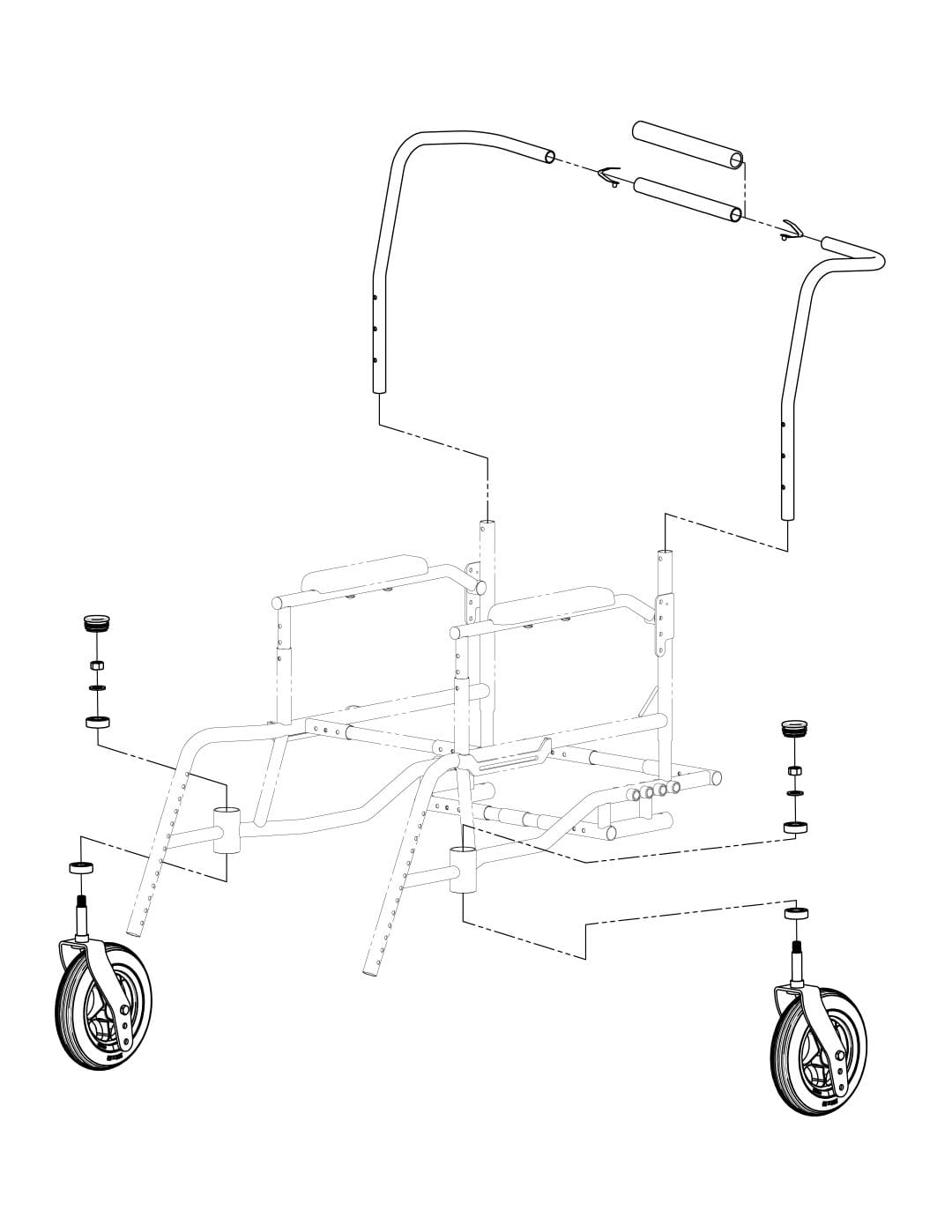
• 2 button clips
• 2 pin clips
• 4 bearings
• 2 M12 washers
• 2 M12 nuts
• 2 38mm plastic caps
Instructions
Push handle
• Insert the right and left sides of the push handle into the padded central tube until the button clips click.
• Insert the push handle posts into the frame tubes to desired height, then secure with the pin clips.
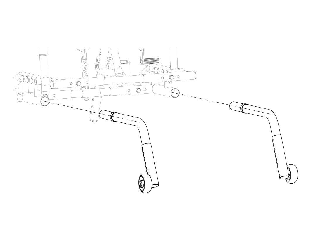
Front casters
• Insert the caster stem into the caster stem housing in the frame. Make sure there are two bearings in each housing (one on the top and one on the bottom).
• Secure the casters with the M12 washers and nuts. Tighten snugly.
• Cover with the plastic caps.
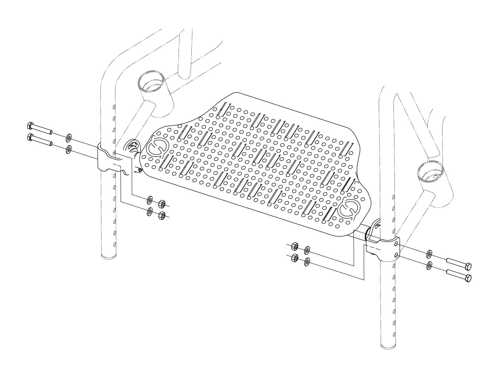
Step 4: Footrest
Tools required
• 10mm open-end wrench
• 10mm socket wrench
Parts required
• 4 M6 hex head cap screws 35mm long
• 8 M6 washers
• 4 M6 nylon lock nuts
Instructions
• Attach the footrest to the frame at desired height using 4 screws, a washer on each screw side and nuts. Screw head should be pointing outward. Tighten snugly.
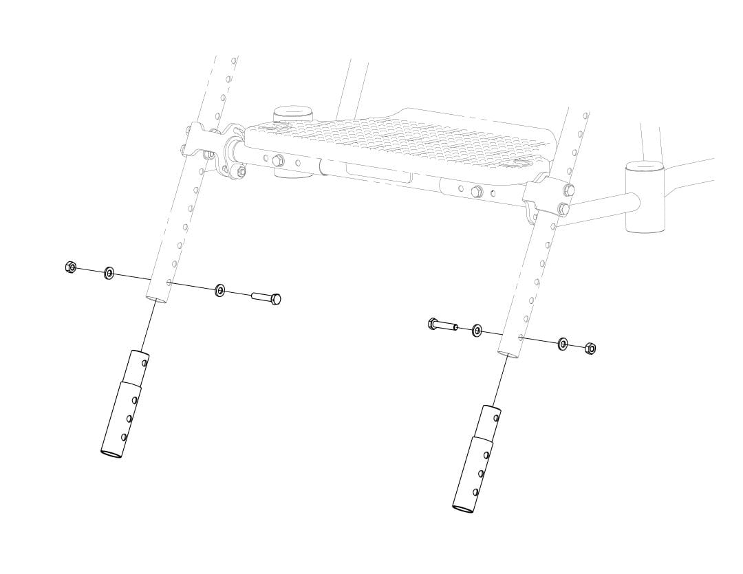
Step 5 (optional): Footrest tube extensions
Tools required
• 10mm open-end wrench
• 10mm socket wrench
Parts required
• 2 M6 hex head cap screws 30mm long
• 4 M6 washers
• 2 M6 nylon lock nuts
Instructions
• Insert the footrest tube extensions into frame posts at desired height. Secure with screws, a washer on each screw side and nuts. Screw head should be pointing outward. Tighten snugly.
Tools required
• Socket wrench
Parts required
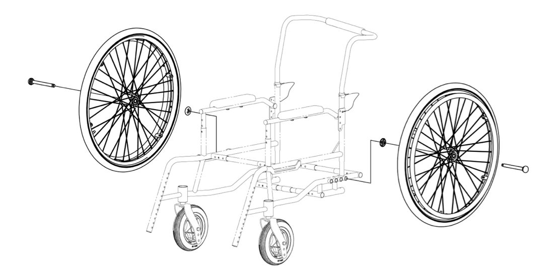
• 2 quick-release axle pins
• 2 bearing covers
Instructions
• Insert the quick-release axle into the rear wheel hubs, pressing the button to retract the balls at the other end of the axle. Use the socket wrench to help slide the axle all the way into the hub.
• Insert the rear wheels into the desired axle position by pushing the button to retract the balls at the end of the axle and inserting the axle pin into the sleeve.
• Make sure the axle has completely gone through the axle sleeve, the balls should be visible out of the sleeve.
• Release the axle button and make sure the rear wheels are latched securely into place by holding the wheel from the hub and wiggling in all directions. It should not have slack, but some may be acceptable.
• Place the plastic caps into the axle sleeves with no caps.
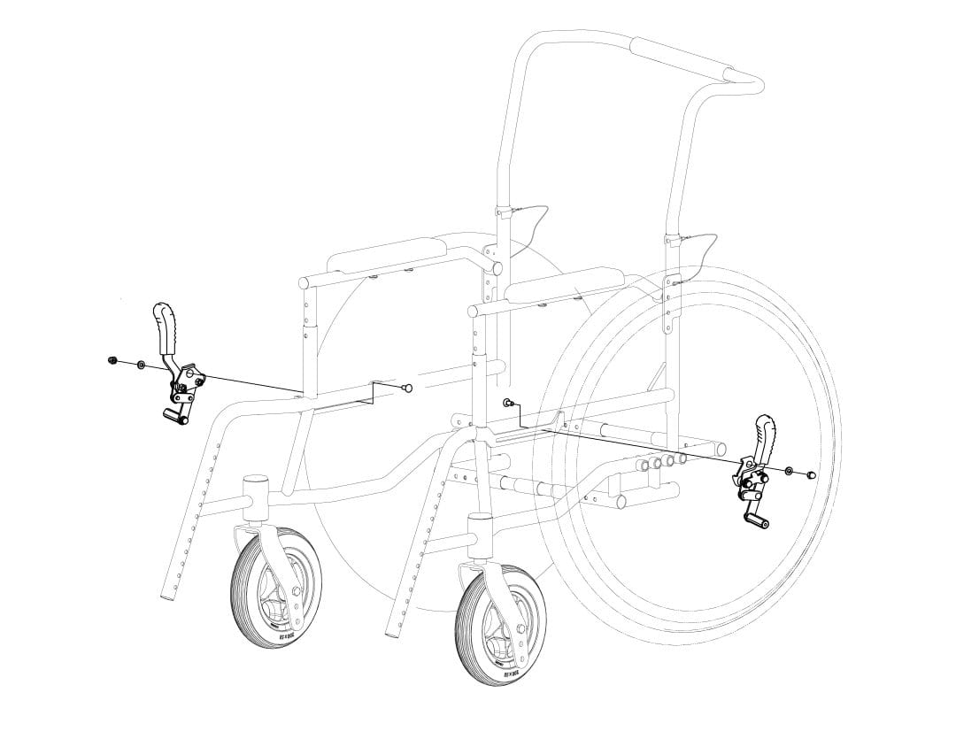
Step 7: Wheel locks
Tools required
• 10mm open-end wrench
Parts required
• 2 M6 special screws 16mm long
• 2 M6 washers
• 2 M6 U-nuts with cap
Instructions
• Attach the wheel lock to the frame slot by using a special screw (inner face), washer and cap nut on each side.
• Before tightening the screws, move the wheel locks to desired position and tighten the nuts.
• Apply the locks and check that they hold the tires firmly in place without interfering with them while rolling, and that they are easy to activate.
• Repeat steps if needed.
Tools required
• Phillips screwdriver
Parts required
• 4 M6 Phillips head pan screws 10mm long
• 2 M6 knobs
Instructions
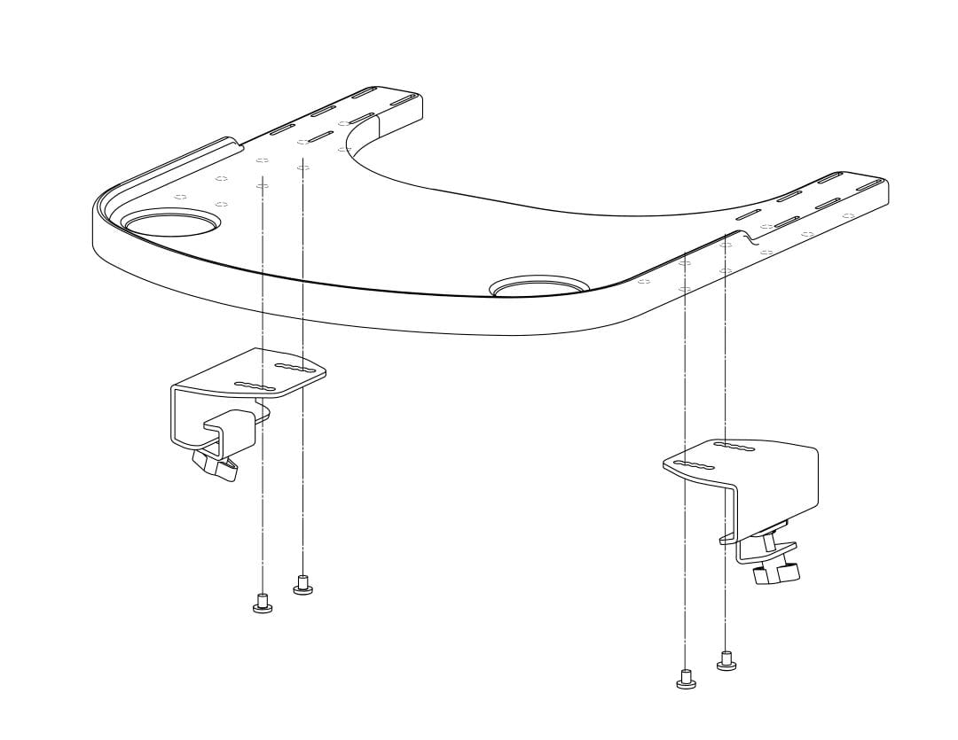
• Secure the mounting brackets to the tray with two Philips screws on each side. Make sure the brackets are positioned at the same distance of the frame width (small, medium or large). Tighten the screws snugly.
Section 2: Seat Unit Assembly
Step 1: Seat pan and tilt mechanism
Tools required
• 10mm socket wrench
Parts required
• 2 seat pan clamps
• 2 bolts
• 2 M6 washers
• 2 M6 nylon lock nuts
Instructions
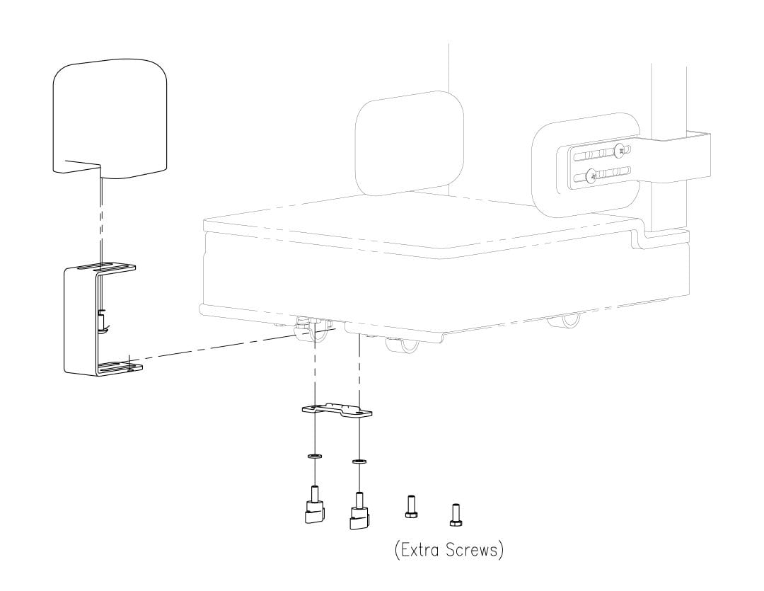
• Attach the clamps to the front seat frame tube and position the seat pan over the seat frame by inserting the “T” ends of the clamps into the seat pan slots on each side.
• Hook the tilt mechanism of the seat pan on the anchor bolt of the frame at desired height.
• Tighten the bolt of the anchor mechanism of the frame.
• Tighten the screws of the seat clamps below the seat pan.
Tools required
• 10mm open-end wrench
• 10mm Socket wrench
Parts required
• 2 M6 Hex head cap screws 35mm long
• 10 M6 Hex head cap screws 10mm long
• 8 M6 Washers
• 4 M8 Washers
• 4 M6 nuts with flange
Instructions
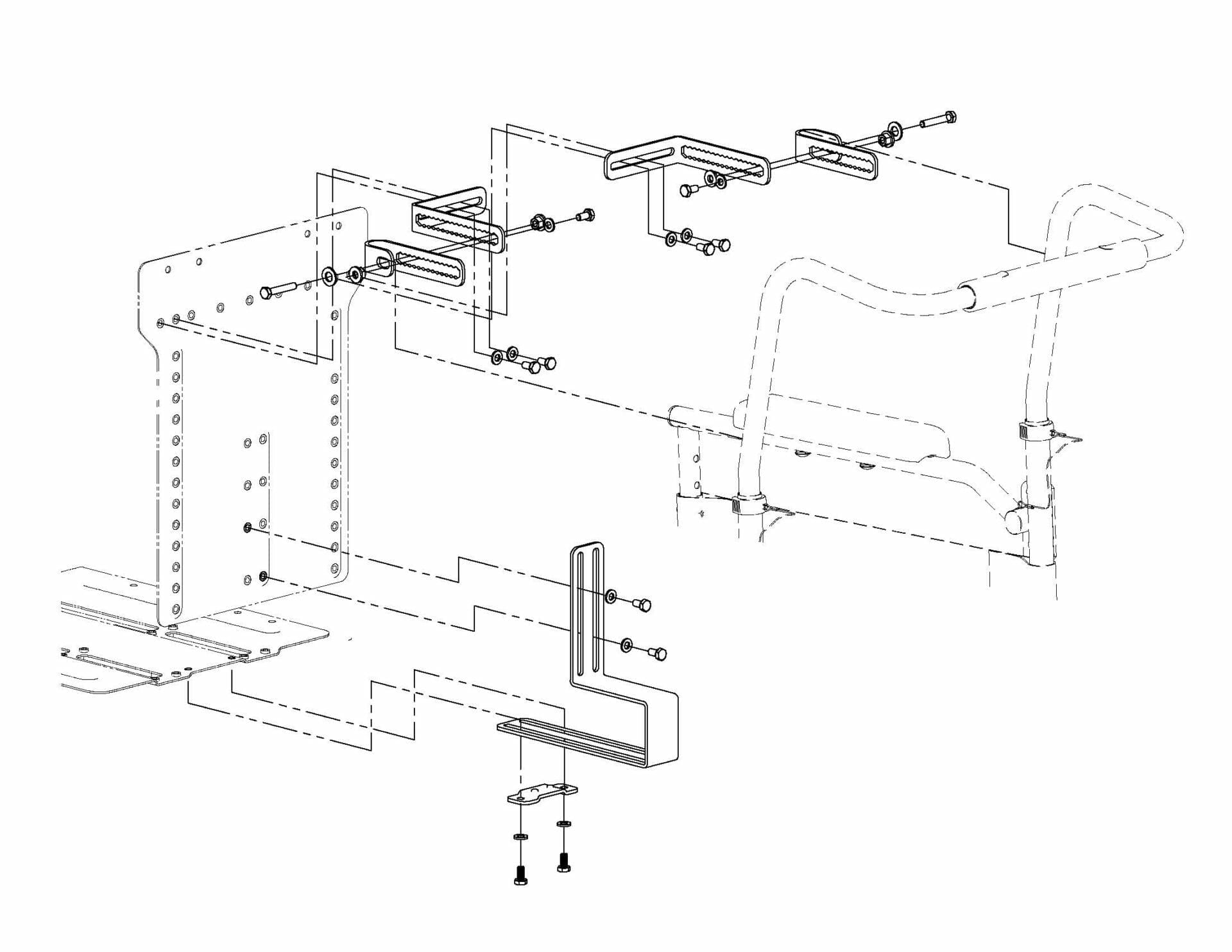
• Attach the backrest pan flat mount under the seat pan with 2 short screws and washers. Insert the longer end of the backrest bracket between the seat pan and the flat mount and secure.
• Attach the backrest pan to the front face of the bracket with 2 short screws and washers in diagonal.
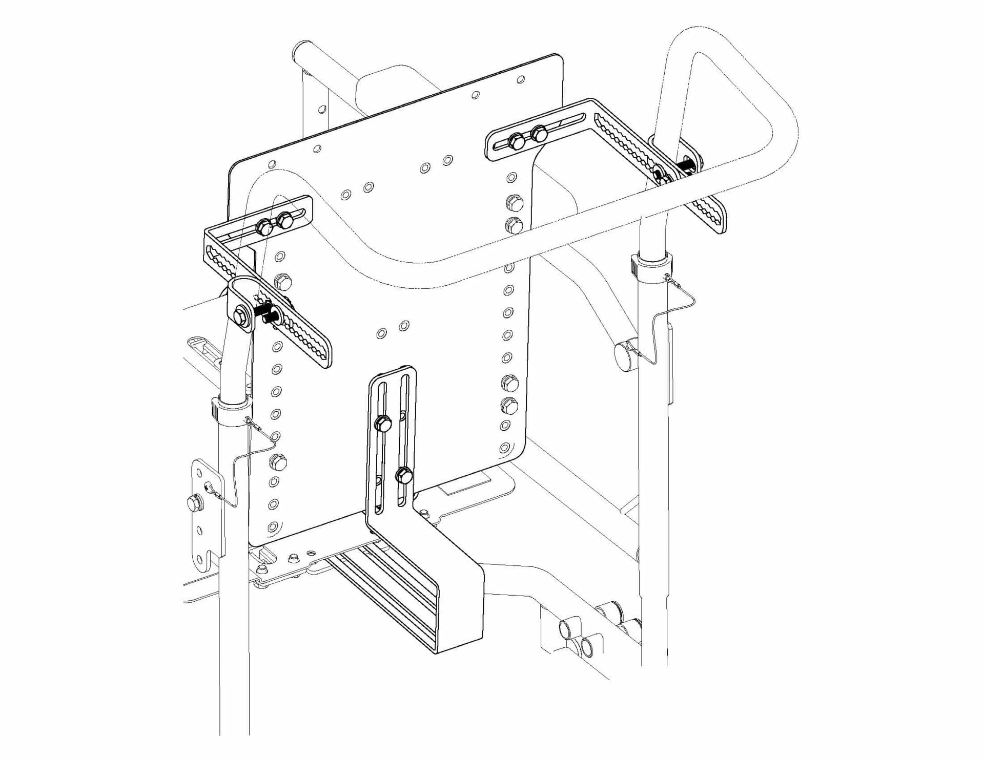
• Attach the “L” brackets to the top of the backrest pan with 2 short screws and washers on each side.
• Attach the “U” brackets to the outer face of the “L” brackets with 2 short screws, washers and nuts with flange.
• Attach the “U” brackets to the back-frame posts with 2 long screws, M8 washers, and nuts with flange.
• Adjust the “U” brackets accordingly to desired backrest recline.
• Tighten all screws snugly.
Tools required
• 10mm socket wrench
• Phillips screwdriver
Parts required
• 8 M6 Phillips head pan screws 10mm long
• 8 M6 hex head cap screws 10mm long
Instructions
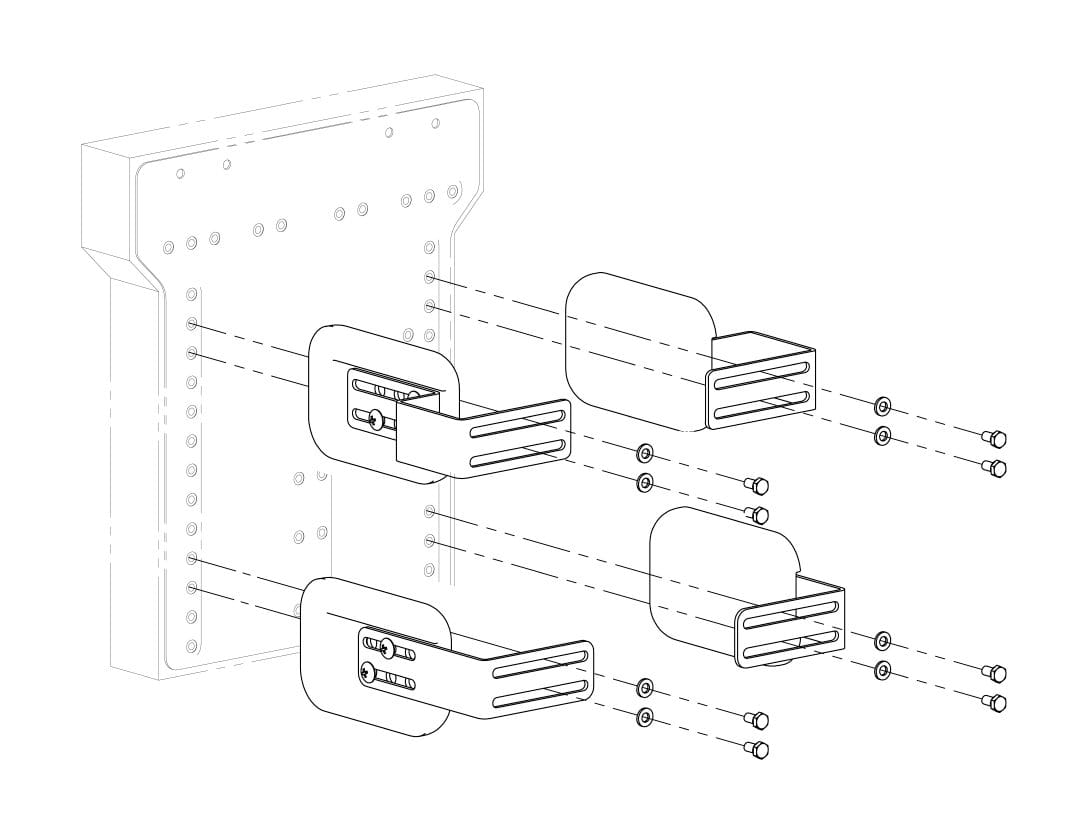
• Attach the pads to the lateral support brackets with 2 Philips screws each. Pads should be in the inner face of the brackets.
Tools required
• 10mm socket wrench
• Phillips screwdriver
Parts required
• 8 M6 Phillips head pan screws 10mm long
• 8 M6 hex head cap screws 10mm long
Instructions
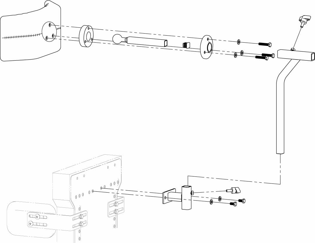
• Assemble the headrest in the following order: connect the ball-head mount and round bracket with the headrest pad and round cap by using 3 30-mm long screws and washers. Cover the other end of the ball-head mount with a plastic cap.
Tools required
• 10mm socket wrench
Parts required
• 4 M6 hex head cap screws 10mm long
• 6 M6 washers
• 2 M6 nylon lock nuts
Instructions
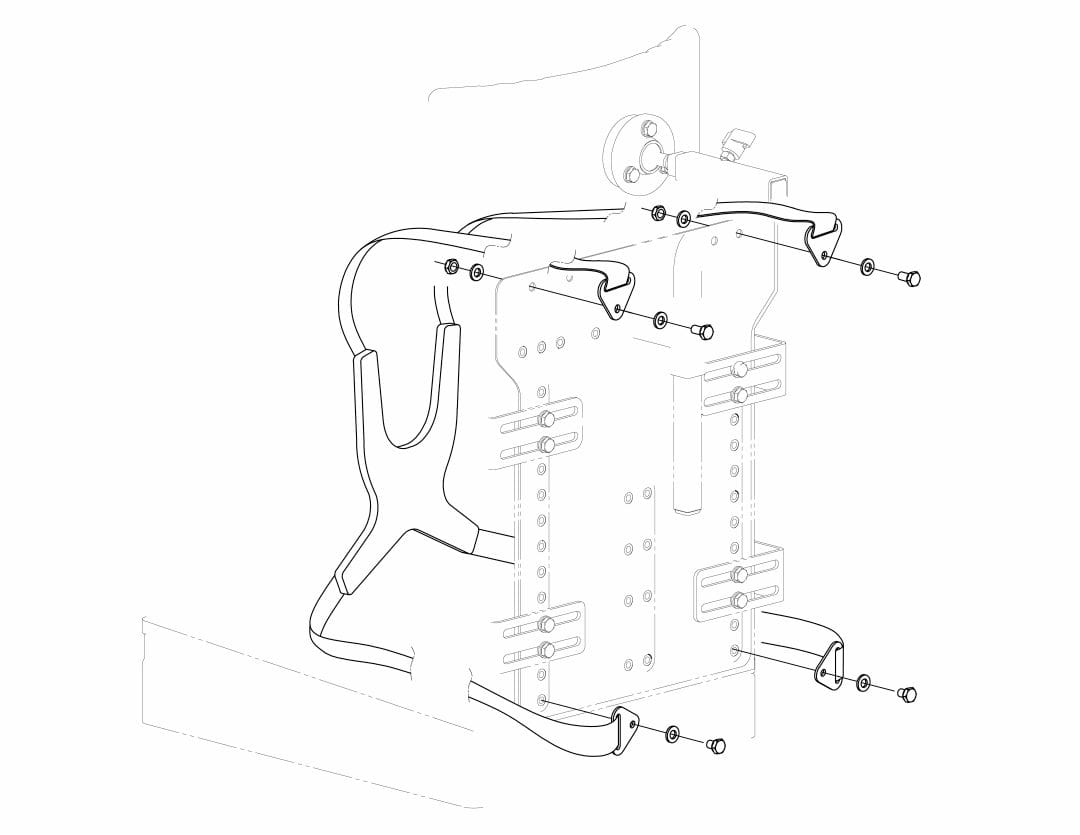
• Attach the top ends of the chest harness to holes in the top edge of the backrest pan by using 2 screws, washers and nuts.
Tools required
• 10mm socket wrench
Parts required
• 2 M6 hex head cap screws 10mm long
• 4 M6 washers
• 2 M6 nylon lock nuts
Instructions
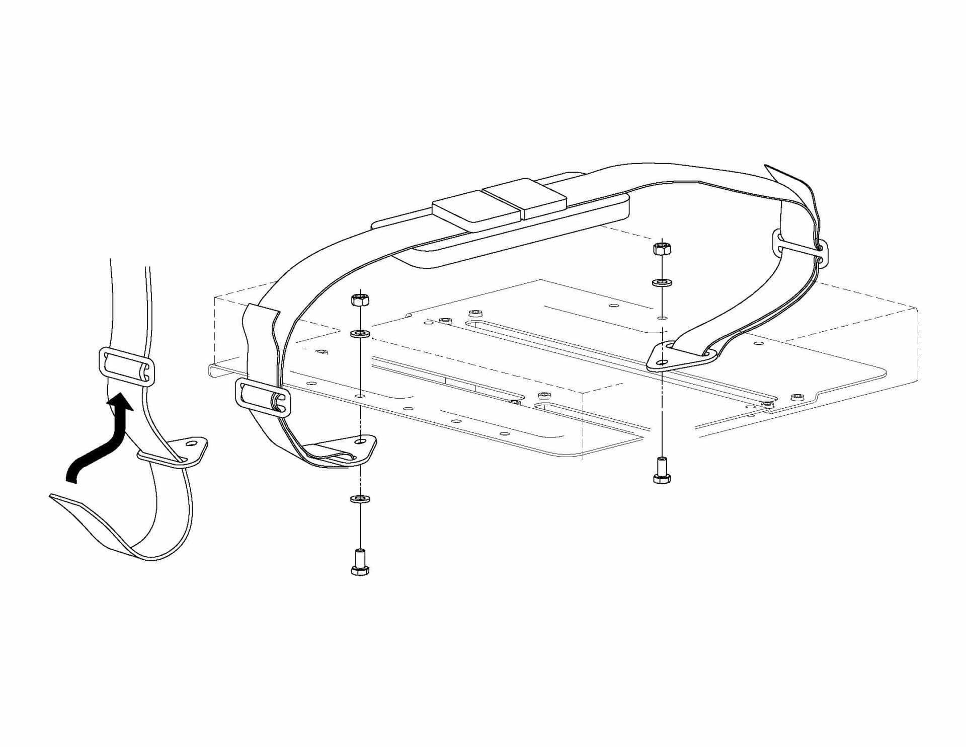
• Attach the pelvic strap flat mounts to the bottom of the seat pan by using 2 screws, washers and nuts. Unbuckle the strap.
Tools required
• 10mm open-end wrench
• Phillips screwdriver
Parts required
• 2 M6 Phillips head screws 10mm long
• 1 attachment bracket
• 2 M6 knobs 15mm long
• 2 M6 hex head cap screws 10mm long
• 2 M6 washers
Instructions
• Attach the abductor pad to the abductor bracket with 2 Philips screws and cover with fabric cover.
Tools required
• Foam knife
Parts required
• No hardware required
Instructions
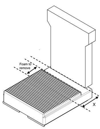
• Adjust the seat depth according to the user’s needs
• Measure the distance from the back of the pelvis to the seat bones in mm
• X = distance from backrest to pre-seat bone shelf = distance from the back of the pelvis to the seat bones in mm + 20-40 mm
• Adjust de pre-seat bone shelf length by cutting the excess foam
Section 3: Adjustments
Step 1: Abductor
Tools required
• 10mm open-end wrench
• Phillips screwdriver
Instructions
If attached with screws:
• Loosen the hex screws that attach the abductor mount to the seat pan
• Move the abductor back or forth to the desired position
• Tighten hex screws snugly
• For additional adjustment: loosen the Philips screws that attach the abductor pad to the mount and slide the pad back or forth. Tighten Philips screws snugly.
If attached with knobs:
• Loosen the knobs below the abductor
• Move the abductor back or forth to the desired position
• Tighten knobs snugly.
Tools required
• 10mm open-end wrench
• 10mm socket wrench
• Phillips screwdriver
Instructions
To adjust armrest height:
• Remove the 2 M6 hex head cap screws in the back and the 2 M6 Philips pan head screws in the front.
• Move the armrest to the desired height.
• Align the holes in the tube and reinsert the Philips screws in the external side and the washer and nut on the internal side.
• Align the holes in the back of the frame with the hex screws.
• Tighten snugly.
To adjust armrest pad position:
• Remove the 2 M6 Philips pan head screws under the pads.
• Move the pads to the desired position.
• Reinsert the spring washers and the Philips screes into the tube holes and tighten snugly.
Tools required
• Phillips screwdriver
Instructions
• Make sure wheel locks are not activated.
• Make sure wheel locks are not activated.
• Push the button on the rear wheel axles to retract the balls at the other end and remove the rear wheels.
• Remove the plastic cap of the desired axle sleeve position in the frame (use the screwdriver).
• Insert the rear wheels into the desired axle position by pushing the button to retract the balls at the end of the axle and introducing the axle pin into the sleeve.
• Make sure the axle has fully gone through the sleeve, the balls should be visible out of the sleeve.
• Release the axle button and make sure the rear wheels are latched securely into place by holding the wheel from the hub and wiggling in all directions. It should not have play, some play maybe acceptable.
• Place the plastic caps into the axle sleeves with no caps.
• Adjust the wheel locks as explained in step 10.
Tools required
• 10mm open-end wrench
• 13mm open-end wrench
• 10mm socket wrench
• Phillips screwdriver
Instructions
To adjust the height:
• Remove the 4 hex screws that attach the footrest to the frame tubes.
• Move the footrest up or down to desired position.
• Align the holes of the tube with the holes of the footrest mount.
• Reinsert the 4 hex screws. The screw head should be facing the external side of the tube and the washer and nut the inner side.
• Tighten snugly.
To adjust depth:
• Loosen the Philips screws under the footrest pan.
• Slide the footrest pan or forth to desired position.
• Tighten back screws snugly.
• For additional adjustment: Remove the Philips screws and washers under the footrest pan and move the pan over additional position holes. Reinsert screws and washers and tighten snugly.
To adjust angle:
• Remove the M6 hex screw on each side of the footrest tube axle.
• Loosen the M8 hex screws on each side of the footrest tube axle.
• Rotate the footrest pan to the desired angle. Make sure both sides have the same angle.
• Insert the M6 hex screws and washers on both sides to secure position and tighten snugly.
• Tighten M8 hex screws snugly.
Tools required
•10mm open-end wrench
Instructions
To adjust the height:
• Loosen the knob on the vertical headrest mount tube
• Move the headrest up or down to desired position.
• Tighten knob snugly.
To adjust the depth:
• Loosen the knob on the horizontal headrest mount tube
• Move the headrest back or forth to desired position.
• Tighten knob snugly.
To adjust angle & rotation:
• Loosen the 3 hex screws on the base of the ball mount on the headrest
• Turn and rotate the headrest to desired position.
• Tighten all screws snugly.
Tools required
• 10mm socket wrench
• Phillips screwdriver
Instructions
To adjust the height:
• Remove the 2 hex screws that attach the lateral support to the backrest pan.
• Move the support up or down to desired position.
• Align the support slots with the holes in the backrest pan.
• Insert hex screws and washers and tighten snugly.
• Repeat with other supports.
To adjust the width:
• Loosen the 2 hex screws that attach the lateral support to the backrest pan.
• Move the support in or out to desired position.
• Tighten hex screws snugly.
• Repeat with other supports.
To adjust the depth:
• Loosen the 2 Philips screws that attach the pad to the support bracket.
• Move the support back or forth to desired position.
• Tighten Philips screws snugly.
• Repeat with other supports.
Tools required
• 10mm socket wrench
Instructions
• Loosen the screws of the “U” brackets in needed.
• Remove the pin clip.
• Move the push handle to the desired height.
• Align the inner tube holes with the outer tube holes and insert the pin clip on each side.
• Tighten the screws of the “U” brackets.
Tools required
• 10mm socket wrench
Instructions
• Loosen the hex screws of the seat-to-backrest attachment bracket below the seat pan.
• Remove the hex screws that attach the “L” brackets to the “U” brackets in the back-frame posts.
• Loosen the 35mm-long hex screws of the “U” brackets in the back-frame posts.
• Move the backrest forward or backward to the desired seat depth.
• Tighten the hex screws of the seat-to-backrest attachment bracket below the seat pan.
• Recline the backrest to the desired angle and hold it in place.
• Insert the hex screws, washers and nuts with flange that attach the “L” brackets to the “U” brackets in the back-frame posts. Tighten snugly.
• Tighten the 35mm-long hex screws of the “U” brackets in the back-frame posts.
Tools required
• 10mm socket wrench
Instructions
• Loosen the bolt of the anchor mechanism of the frame.
• Loosen the 4 hex screws of the seat clamps below the seat pan. (If needed, you may need to remove the abductor and the abductor mount to make this adjustment.)
• Loosen the hex screws that attach the “L” brackets to the “U” brackets in the back-frame posts.
• Loosen the 35mm-long hex screws of the “U” brackets in the back-frame posts.
• Unhook the tilt mechanism of the seat pan and move the seat pan up or down to desired angle.
• Hook the tilt mechanism on the anchor bolt.
• Tighten the bolt of the anchor mechanism of the frame.
• Tighten the 4 hex screws of the seat clamps below the seat pan.
• Tighten the hex screws that attach the “L” brackets to the “U” brackets in the back-frame posts.
• Tighten the 35mm-long hex screws of the “U” brackets in the back-frame posts.
• If needed, adjust the seat depth and backrest recline as explained in Step 8.
Tools required
• 10mm open-end wrench
Instructions
• Loosen the U-nuts with cap.
• Move the wheel locks back or forth to the desired position.
• Tighten the nuts. Apply the locks and check that they hold the tires firmly in place without interfering with them while rolling and that they are easy to activate.
• Repeat steps if needed.

